Search the Community
Showing results for tags 'es9038'.
Found 2 results
-
 I run my own reviews, build logs, news, troubleshooting articles, etc website. My site is free of ads or trackers if anyone is interested in checking it out: www.HallmanLabs.com I usually do reviews on Op-amps and DAC accessories, like the AudioQuest Jitterbug or Sbooster Vbus2. This time I am comparing two completely separate DACs. The Burson Audio Play vs my custom ES9038Pro DAC. The only input the Burson "Play" has is USB input! This limits the way I can get specific test signals into the unit for comparison to my ES9038Pro that has 3 input interfaces. I am looking for recommendations on good software for checking jitter, phase, BER etc. I know of a few, but some are unable to play nicely with Windows 10 x64 Pro. A good example being Audio Rightmark, sometimes works and sometimes doesn't. http://audio.rightmark.org/index_new.shtml I have a pretty decent digital oscilloscope (Siglent SDS1202X-E 200 MHz w/ serial decode included free) and a dual function generator, but how can I use this when digital input is my only option. Edit: I did notice that my DDS function generator has TTL output in the rear. That might be handy in a situation like this.
 -
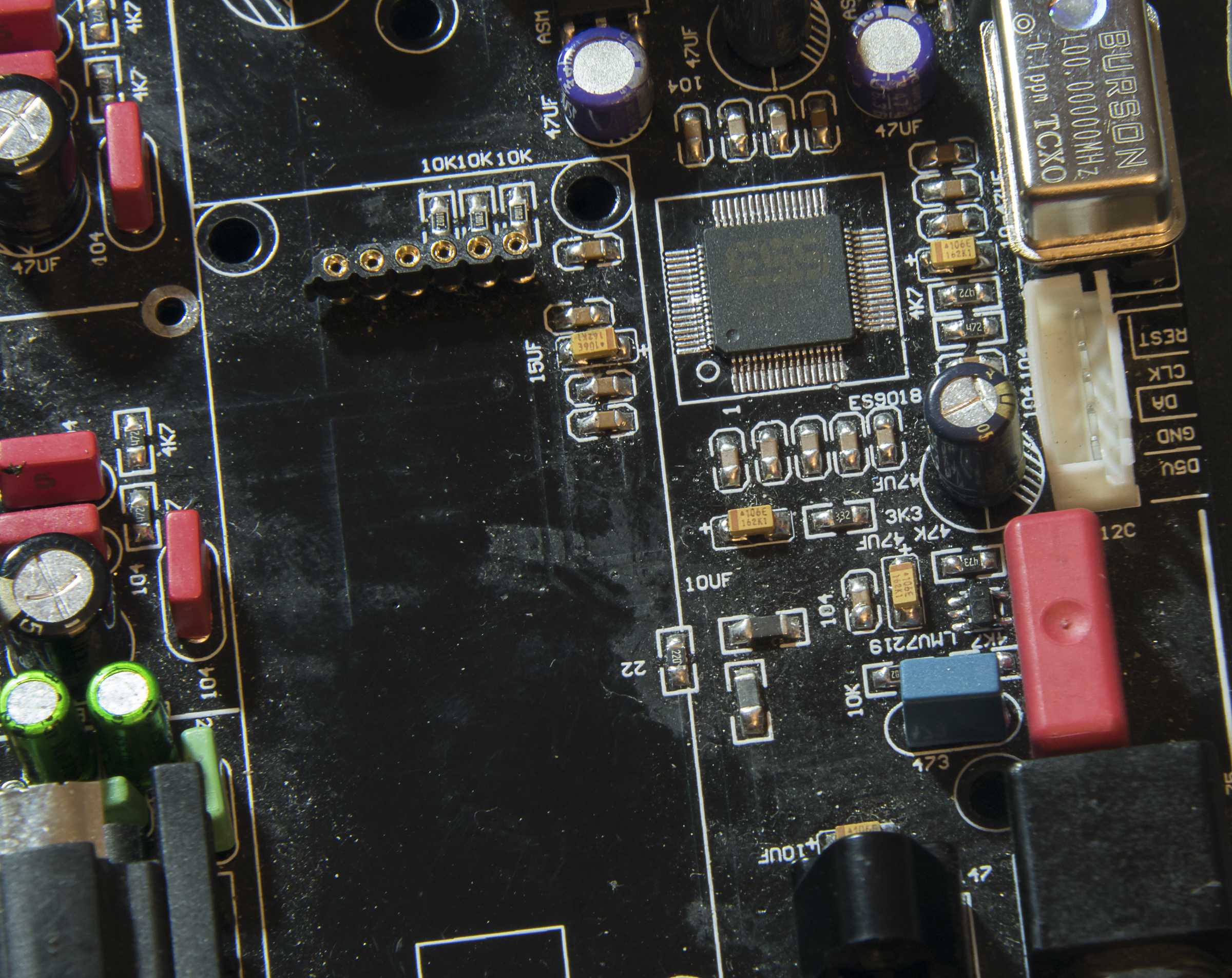
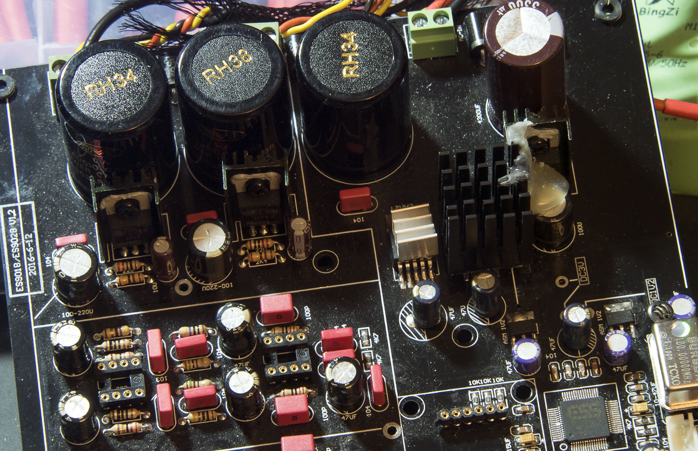
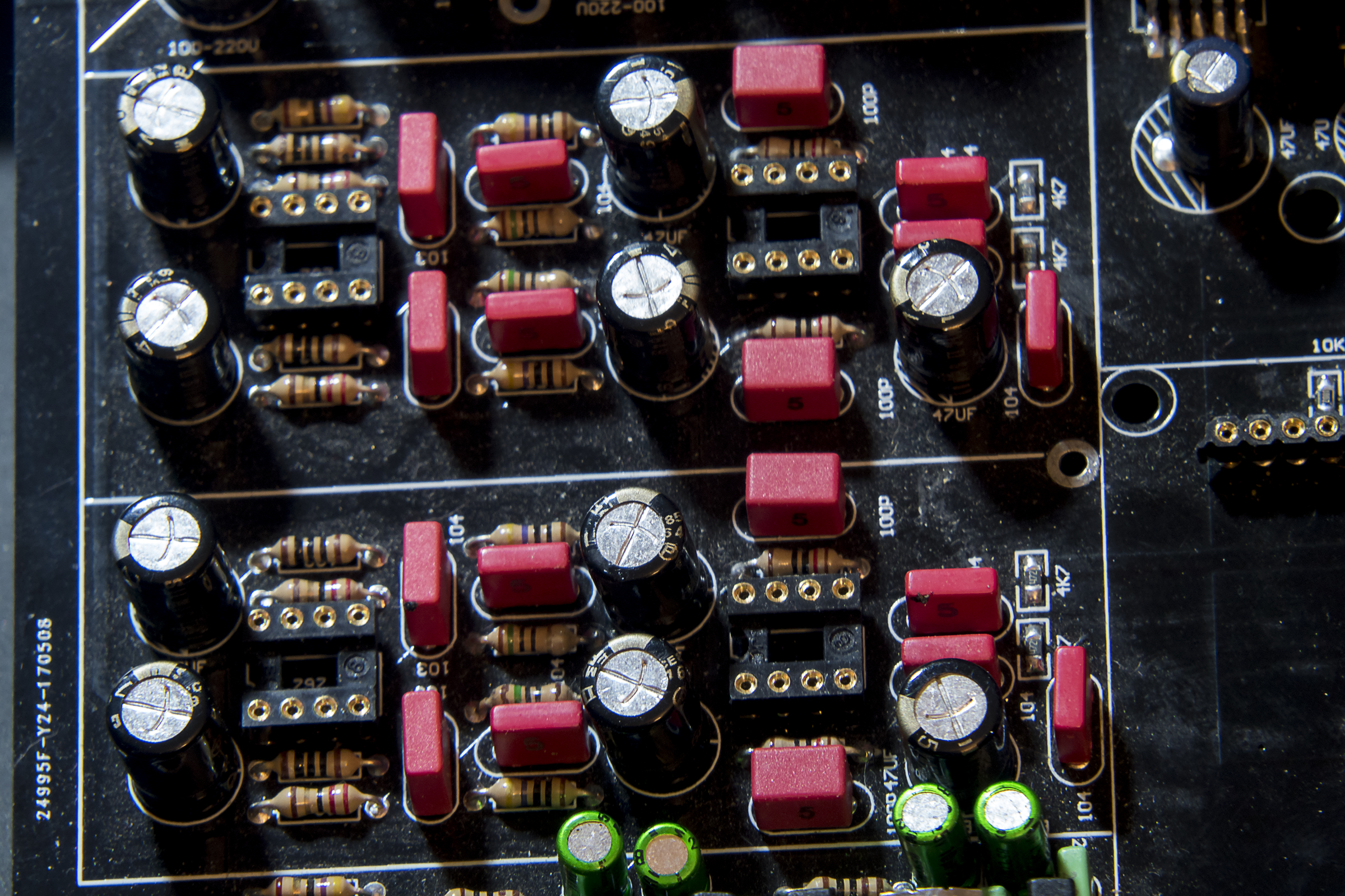
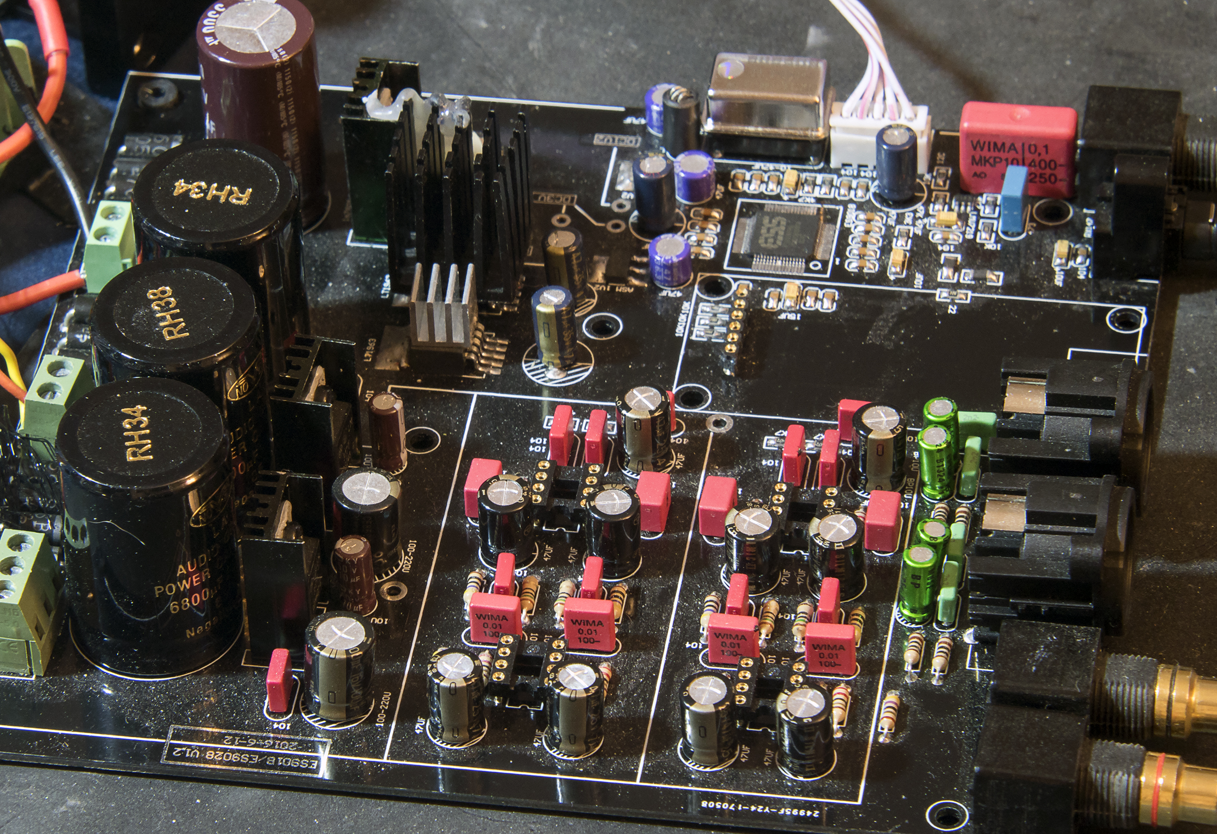
Before I go into this kind of topic I wanted to say hello to the community! My name is Keith and I am 30 years old, just joined this site after many years reading it. I run my own website that is a non-profit HiFi (no ads, trackers, cost, etc.). The address is just www.HallmanLabs.com and I welcome anyone to come by and check out the site and make suggestions or comments on my articles and reviews soon. Request things in the comments and you might be surprised what you see one day! I added an article about the troubleshooting here if anyone wants to read it there instead: https://hallmanlabs.com/2018/02/06/houston-we-have-lost-contact-es9038p-dac-troubleshooting/ Reviews are what has my butt to the fire, I just lost my ES9038Pro DAC this weekend while trying to test out a simple dedicated TCXO module ($40 on Ebay), maybe lost maybe not. My mistake came when I decided to give the module a parallel hookup with one of my DAC's transformers; 6Vrms inputs since it only needed 5V min I knew that was fine. The only problem is that my transformer is rated for 6V @ 2.5A x2 (twin secondaries) and this module only takes up to 0.5A. Now I can't be sure I even damaged anything yet, I unplugged it pretty quickly. I have taken voltages from all over the DAC including all the LT1963 and other regulators/LDOs in a list below. I am hoping by giving enough data someone can spot the cause of my NLOCK problems or point me in the right direction? The oscillator module I used is just like this except that mine came without any oscillator so you can install your own. Or you can do what I did, put an oscillator socket and this board will take either full can or half size can sockets. The module is advertised for DACs and CD players, so I assume 100MHz is inside the operating range: https://www.ebay.com/itm/0-5PPM-16-9344-8-4672-Mhz-Low-Jitter-TCXO-Clock-Module-Golden-Oscillator/132170134611?hash=item1ec5f43453:g:YrkAAOSwAL9UgBwg Ever since I plugged that thing in my DAC has still worked in every way except what matters, playing music. I can go through all the menus, change filters and tell the unit to reset, change inputs or volume. No matter what I do (I2S in, Optical in, etc.), that "NLOCK" message is always displayed. I even removed the DAC from my enclosure because I have seen it work outside, but not inside (dead short caused by the IR receiver on display touching enclosure). I have already gone through insanely bizarre issues with this DAC. That makes me want to fix it even more vs. having to buy another one when I don't even know for sure what is wrong with this one. The first big question for me to ask: What is NLOCK that shows on my DAC screen? I assume the ES9028 has a very similar menu system/OS as the ES9038 considering they can go on the same PCBs except the ES9038 is only to get 6V, not 9V. I have spent hours reading and researching on these devices. I bet even the ES9018 has similar menus (they also can go into the ES9038 DACs if you want to downgrade!). Answer: NLOCK = No Lock and is shown when the DAC can't lock onto a signal. The usual train of thought points you at the PLL (Phase locked loop), which is on the actual ES9038Pro IC, we believe. One important thing to note: if NLOCK is "on"/displayed there is never any output at all, not even static/hiss/etc. So if NLOCK is on, output is off. Big Question #2: My DAC did not say DOP at the top before this happened, it was either PCM or DSD. Using an Amanero you don't need DOP. How did my DAC get switched into DOP mode for every input? Is there a way to refresh these DAC's with a new BIOS or something similar? I had the ES9038PRO DAC running without issues for at least 2 weeks, maybe 3 using various discrete op-amp setups and taking notes for the reviews. I showed my readers all the I2S related accessories tweaks that I had available to test. This DAC accessory post on my site has the 2nd most views of ANY post/page next to my original review for Burson Audio that basically started the site. Because of this interest I wanted to test this seemingly harmless Dedicated TCXO module for supposed quality increases, which has everything it needs to function except 2 AC lines (rated max of 12Vrms). I was also testing/measuring my twin 6V transformer, this was the power I sent to the TCXO module. I felt the voltage regulator on the TCXO was getting really hot so I pulled it in less than 5 mins, the DAC was only turned on with it for about 1-2 mins. I can't find any signs of damage even with a 600x microscope to any component, but the screen always says (NLOCK w/ mode DOP & volume level # indicator) no matter what I try I can't get this guy to come back to life for me and play music… Even though I put the original oscillator back in + fixed the only wires altered for this dedicated TCXO module. In the terminal block I removed the extra 2 wires holding the dedicated TCXO power wire into the power inputs of the DAC (they were in parallel), it didn't fix it, still NLOCK. Doing this for all the inputs is what concerns me, but I can't find anything out of spec so far. I don't have a real schematic, so that sucks. Each voltage reference point on the board all read within spec. I can't find even a hint of damage or even a bad solder joint anywhere. I do have 3x 1A fuses inside this setup. Each hot wire in this enclosure has their own 1A fuses, so no more than 1A could pass without breaking multi 1A fuses. The two transformers together can't pull 1A without blowing the main AC fuse in the plug. When I measure the DAC up and running, it usually only shows 0.10A and from there it barely changes. Big Question #3: Do you all think it is possible I killed my ES9038Pro DAC with an oscillator module? Is that even possible? I could really use some help if you all think you might be able to assist me. I am outside the return policy of this DAC, so I would have to buy another if I can't find a problem. I love building stuff until this happens and I have nobody to ask for help that knows the device inside and out. Here are the voltage readings I got on the following components: Near the three LA Nover capacitors, there are two LDOs right in front of them. All of these measurements were taken from the output side looking toward the power input side. If it helps I can put the numbers in the pictures. One is a 337T my voltages were (from left to right looking at it and all the following measurements): -13.86V | -27.62V | -15.12V Next to the that is the 317T: 13.85V | 15.11V | 27.57V Then we have the two LT1963 which basically have the same readings so I'll just list one: 15.07V | 9.25V | 9.25V | GND (0V) | 3.3166V | 3.316V Next to the LT1963 (silver heat sink and black heat sinks side by side = LT1963s) we have the LM7805: 9.64V | GND (0V) | 5.07V Then for the DIP8 sockets I read +15.11V and -15.11V exactly on all four of them. There are three more small transistors (one really small C14A). Once again this transistor pair has identical readings for the AMS 1117 1.2 1508: GND (0V) | 1.55V | 3.327V The last power component was the tiny C14A which read: GND (0V) | GND (0V) | 1.66V on the side towards the op-amps and 3.305V | 1.663V on the other. One last thing I wanted to note was the voltage of the power capacitors Left to right, the first RH34 read 27.57V the RH38 read 27.59V the 2nd RH34 read 9.25V and the KMQ Capacitor read 9.65V Oscillator voltages were read as: Top Left: NC | Top Right: 0.572V | Bottom Left: GND | Bottom Right: 3.315V (Orientation for oscillator is from looking straight down on the PCB with the capacitors at the top and the outputs at the bottom. Or to make it simpler, look at picture number two in the OP and these follow that orientation.) It is possible when using the dedicated TCXO module I had the top and bottom flipped which would have sent the 3.3V signal into the DAC. Most of this was designed by myself using parts available and of course the base DAC. However, this one was not a DIY kit, I had to save time and get an assembled kit (DAC only, no transformers or enclosures, no schematic, etc.). I have spoken with the designer many times and he has been helpful, but I think he is away for like 2 weeks.. Please help!