Ncore1
-
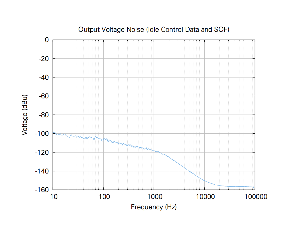
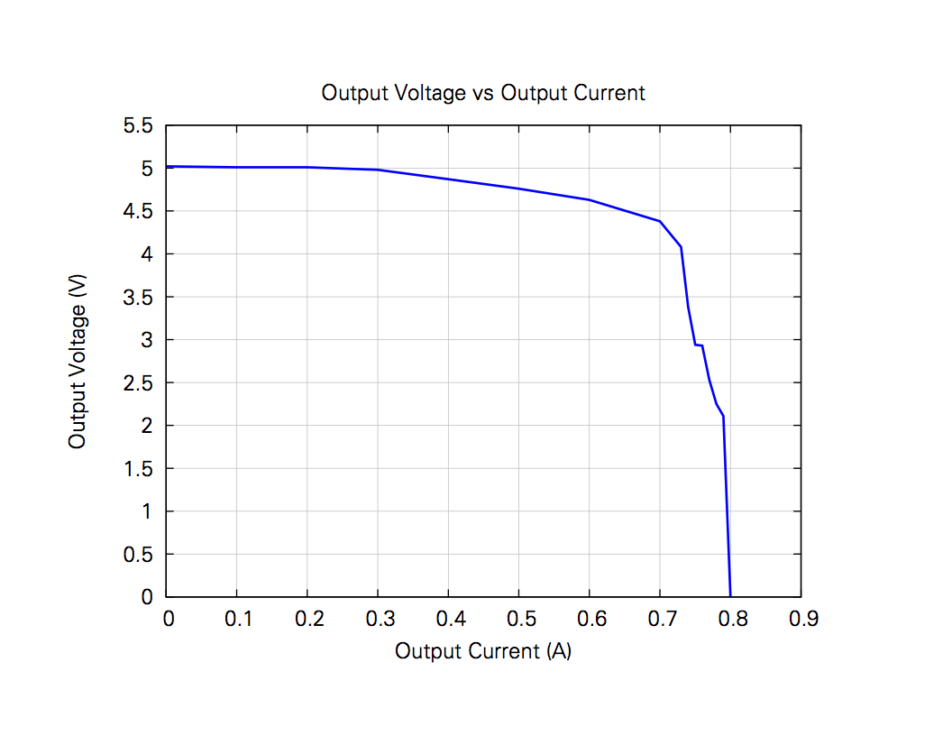
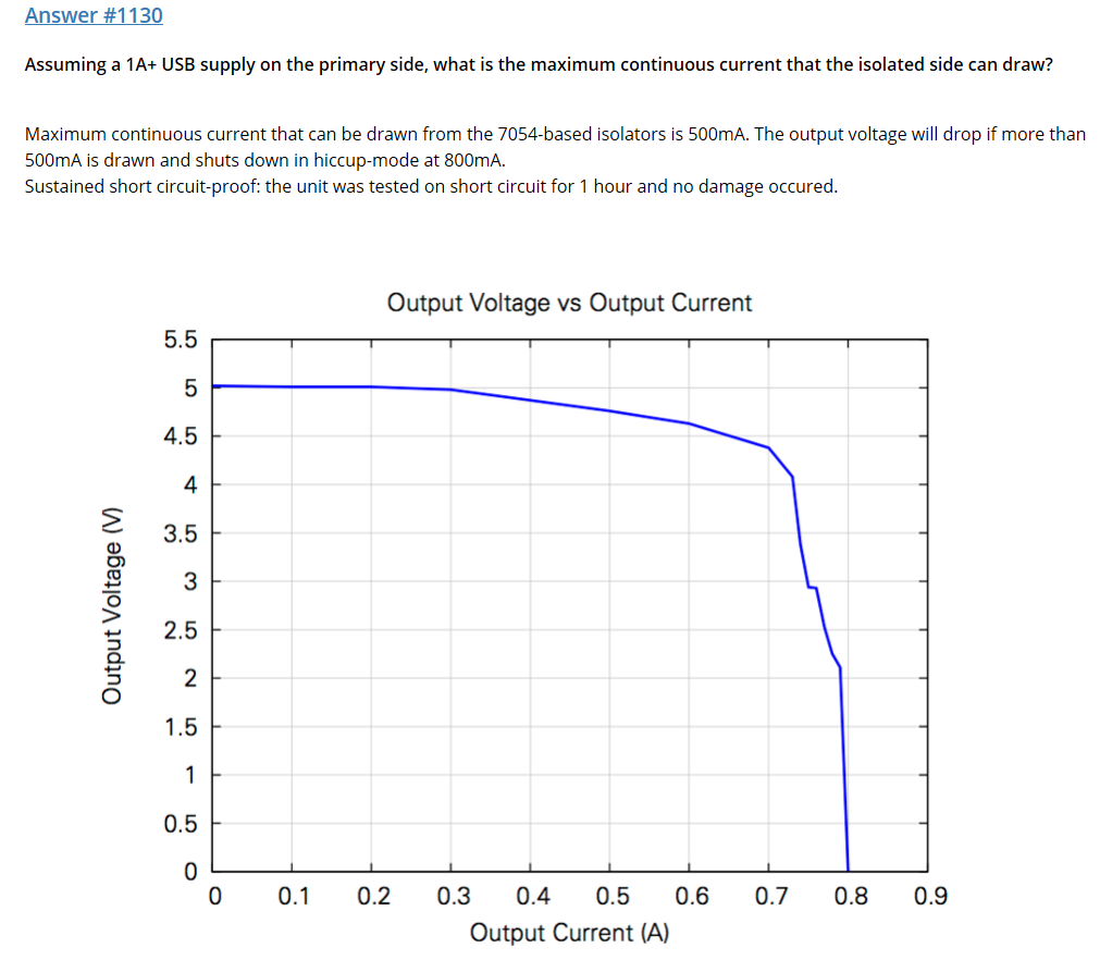
http://intona.eu/en/answer/popular Intona Answer Database (FAQ) Find Answer Answer #1236 Is there any customization possible, for example using a better oscillator? What would you expect by using a "better" oscillator? We measured 12.5ps of RMS jitter on the USB packet clock. A more or less jittery oscillator would not make any difference on this, because of the very low tuned lp-filter in the transceiver's PLL. We use four clocks in our design, all shifted slightly in phase and affected from natural spread spectrum of the isolator chips and other sources. This really helps to bring EMI down and to spread current peaks – e.g. to lower the packet noise. If we would tune everything inside to least jitter, this would rise packet noise and also EMI radiation. One need to distinguish between sample clock in an ADC or DAC: low jitter is the most important, because only the right sample at the right time is the right sample transmission clock of a serial system: BER (bit error rate) or eye mask to be specified clock passing integrated logic: setup and hold times to be met We decided to go for low noise, so spreading clocks and accepting inter-logic-skew was the way to go. Further, clever design of return currents and also a good and low impedance decoupling network of the power supplies are by far more important to meet your needs than looking for the oscillator. Intona Answer Database (FAQ) Find Answer Answer #1240 Is it possible to power the USB Isolator with a linear power supply instead of the PC USB +5V bus? This would be possible if you use an external adapter cable which does split the supply. But please note: Internal voltages are generated by linear regulators. The isolated side is supplied by our own proprietary and very careful designed DC/DC converter followed by linear regulators. The isolated USB output voltage is generated by the Analog Devices ADP125 linear regulator. Because of the isolation barrier, this is really always the same low noise independent from host/computer cable type. Answer #1130 Assuming a 1A+ USB supply on the primary side, what is the maximum continuous current that the isolated side can draw? Maximum continuous current that can be drawn from the 7054-based isolators is 500mA. The output voltage will drop if more than 500mA is drawn and shuts down in hiccup-mode at 800mA. Sustained short circuit-proof: the unit was tested on short circuit for 1 hour and no damage occurred.

-
Ahhh, but when you are told up front that one wine is an expensive highly revered bottle and the othercis a no name cheapo how will that affect your judgement? This thread is based on a commentary by the OP which includes both technical measurements and subjective observation. Its offered as information to the entire readership, in good faith no doubt, but I see problems with the way both are conducted. Its not about saying subjective observations are worthless per se, but they must be controlled to have value. Your personal preferences when driven and affected by bias are worthless to others. The problem is if you spend money and add one of these devices and you compare with and without control you are predisposed to hear that they make a positive difference. You need to test without knowing if its in circuit. Ok, so one technical aspect of a power supply is measured. Shouldc power supply be quiet or noisy? The answer is obvious, would you contradict that it should be quiet? However the next question should be how quiet does it need to be? The real area of interest is does it affect the dac output? So measure the power supply, thats fine its good information, but also measure the dac output and finally perform a controlled listening test. Therecis nothing wrong with technical measurement, its simply objective information that xan be useful to build a picture. Btw that article is absolute rubbish and doesnt demobstrate the point. Firstly the only measurements presented are not actually that similar. Secondly there are many other factors that need to be considered. The driver dispersion for starters will affect the in room sound.....and yes that can be measured. Im sure JA would know this, so his article is a little disingenuous.
-
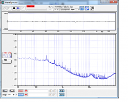
Well, only looking up to 6kHz........
-
As opposed to your biases telling you which one sounds best?
-
There is absolutely nothing wrong with usb for audio. It solves one of the fundamental problems with spdif and aes, the dac word clock is local and doesnt have to be extracted. Mind you, Im not sure jitter is that much of a problem these days and optical will solve any potential noise issue. What none of these tests do is quantify the actual affect on dac output. The obsession with usb data clocks in some of these add on products. Its not the dac word clock. Ask yourself what happens to the usb data when received by the usb chip in the dac. 5 volt noise. How quiet does it need to be? What competent dac wouldnt have further psu filtering and or regulation? Is it relevant beyond bus powered portable dacs? An additional test DM could perform is to measure the DAC output with without these devices and see what differences there are. One thing DMs tests are missing is looking at higher frequency noise, beyond the audio band.
-
DM, Just curious to see what an unterminated noise floor of the 0404 looks like. Also, the specs I read say the 0404 has a max input level of : +12dBV (14.2dBu), so curious how did you calibrate it to 1v? Is the input gain pot turned to zero 1volt? thanks
-
OMG are you for real? The OP was the one who presented technical data! So obviously he felt it was relevant.
-
Do you have anything technical or useful to contribute, or are you just running interference and throwing insults?
-
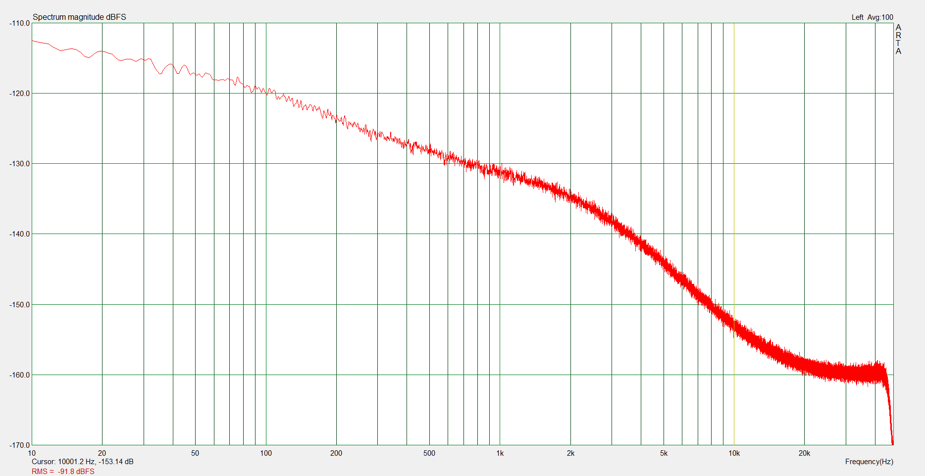
Firstly I am not a moderator on ASR. I contribute there yes, as I do in many forums. Secondly, so what? Whats your point? My contribution here is technical and relevant. But yes I do find it amusing that a number of subjectivists started on the offensive after my reasonable comments regarding the pitfalls of sighted subjective testing. So what is the purpose of your comment here other than an attempt to discredit? OK, perhaps I should have set the parameters of the measurement out, but if you had performed your research correctly you would have found the following information. I did link to the manual. Each analog input is buffered by an input circuit employing the OPA1632 fully differential audio amplifier, selected for its low noise and distortion, and fully-differential input-to-output architecture. The buffer circuit provides attenuation (nominal gain = 0.482, or –6.34dB) and low-pass antialiasing filter functions. The printed circuit board (PCB) layout supports limited board stuff options for experimentation. The full-scale input voltage for the input buffer circuit is approximately 4.2VRMS (or +14.6845dBu) differential You should be aware that a measurement based solely at 10 Hz can be misleading due to the inherent noise ADC suffer at very low frequencies. This can sometimes be improved by changing the filtering for the ADC reference. Lets look at a few results So as best I can make out from the graphs 100Hz Int -105dBu Me -120dBFS DM -80dBV 500Hz -118dBu -128dBFS -90dbV 1000Hz -119dbu -132dBFS -100dBV 5000Hz -140dBu -144dBFS -132dBV All In dBV 100Hz Int -107 Me -103 DM -80 500Hz Int -120 Me -111 DM -90 1000Hz Int -121 Me -114 DM -100 5000Hz Int -142 Me - 127 DM -132 So yes I think my results are significantly more consistent with the manufacturers. I eyeballed them and took the different reference levels into account. Hence my comments, even if I didn't fully expand on them. Yes DMs Measurements do have a fair amount of spuria as noted even on the reference measurement. Oh BTW I didn't take DM "to task" over the reference level, I simply asked what it was. So wheres the misinformation? You can apologise if you want. Other things, ref the measuring on same PC, I was also assuming there was an issue with grounding, my best guess to the discrepancy. Even DM commented upon his surprise at his Intona measurements.
-
Sorry to disappoint but I have no association with or interests in the audio industry whatsoever. Please go to the Intona website and peruse all the publicly available data on the products USB conformance testing. For info I have owned a Regen, but it doesn't solve what I consider to be a fundamental (potential) problem. After a lot of research I chose the Intona product. The data that was presented by the OP just didn't seem correct to me, which is why I checked it out. Bear in mind if you look at the OPs own comments, he also seemed a bit bemused by the Intonas PSU measurements. As I have already done the research I thought it might be useful to share the information, and yes, I am somewhat bemused that anyone would consider the Intonas eye pattern to be a problem. As I mentioned, the pattern I posted earlier is a far end measurement. You may want to look up the consequences to high frequency waveforms. Please ask ifi for the actual far end eye pattern of their device, not an "artists impression". Secondly ask them (or John) to demonstrate (not theorise) the effect of improving rise time from good to slightly better, has on dac output.
-
....mmmmmmm, sorry if I don't take Johns input too seriously. He has his product to promote. Intonas signal integrity is tested and results shown. Its good. IIRC the waveform shown above is actually a far end measurement. Jitter is good at 12ps. I suggest you ask John to provide the same data for the regen and, far more importantly, demonstrate (not theorise) how his improved signal integrity actually helps. You should always bear in mind that at the end of the day the DAC output is the important thing. Things like slightly sharper rise times may not be helpful, could even increase current flows and noise.
-
....mmmmmmm, sorry if I don't take Johns input too seriously. He has his product to promote. Intonas signal integrity is tested and results shown. Its good. I suggest you ask John to provide the same data for the regen and, far more importantly, demonstrate how his improved signal integrity actually helps. You should always bear in mind that at the end of the day the DAC output is the important thing. Things like slightly sharper rise times may not be helpful, could even increase current flows and noise.
-
The PCM422EVM is brilliant. Best bit is it only $150. Buy direct from TI. PCM4222 Evaluation Module (EVM) - PCM4222EVM - TI Tool Folder
-
Where did you get that the intona has poor signal integrity? See eye pattern below. It is true that they had some compatibility issues which appear to be mostly fixed. I went to edit my previous response but it had timed out. If the intona is working within its 5v capability, its quiet. No need for additional supplies. Not to mention of course, depending on how they are configured, could easily cause problems which the intona solved. So you are absolutely right with your comments there. BTW the regen has a God awful SMPS which spews out RF. Must go linear with that one. Plus has the potential to cause problems (noise) with its ground lift resistor. It would be an interesting exercise to contact all the manufacturers in this test to see if they can provide the same test data and USB compliance test data for their products.
-
Well I would say that the intonas PSU is quiet, but has limitations which Intona describe on their website. I would have to test it at higher currents to see if any issues develop, but clearly up to the 300mA that I tested it is fine. A current hungry DAC might cause a problem. The Meridian explorer I measured was only 150 mA. The next question to ask is what, if any of the USB noise makes it onto the DAC output. The other thing to note is that these tests are not performed using real loads. I will try and hook up the dac also and see what appears on the supply.